|
|
ESV30 series three-way ball valve |
|||||||||||||||||||||||||||||||||||||||||||||||||||||||||||||||||||||||||||||||||||||||||||||||||||||||||||||||||||||||||||||||||||||||||||||||||||||||||||||||||||||||||||||||||||||||||||||||||||||||||||||||||||||||||||||||||||||||||||||||||||||||||||||||||||||||||||||||||||||||||||||||||||||||||||||||||||||||||||||||||||||||||||||||||||||||||||||||||||||||||||||||||||||||||||||||||||||||||||||||||||||||||||||||||||||||||||||||||||||||||||||||||||||||||||||||||||||||||||||||||||||||||||||||||||||||||||||||||||||||||||||||||||||||||||||||||||||||||||||||||||||||||||||||||||||||||||||||||||||||||||||||||||||||||||||||||||||
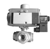
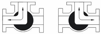
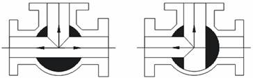
Characteristics: Good sealing performance. Profile: Three-way ball valve can be divided into L-form and T-form. L-form can be used to change the flow of mediumand connect two channels which are perpendicular to each other. While T-form can divide and combine themedium and change the flow direction. They can also connect three channels or connect two of them. The valve realizes starting and stopping by taking the advantage of the sphere rotating around the valve pole. The ball on the pipe is mainly used to cut off and change the flow direction of the medium. The ball valve’s opening and closing is only need 90° rotation, so it is easy realizing automation and remote control. Pneumatic device, electric device and hydraulic device can be chosen to add it.
The main parameters:
Product Standard Table:
Particular Requirements for Product List:
Connectivity method
Three-way L-form Three-way T-form
  2.1.Threaded type
Reference dimensions
2.2.Flange type
Reference dimensions Unit: mm
Note: LBS is pressure unit of American standard, JIS is pressure unit of Japanese standard.
1. Valve torque table
Note: in=2.54×2.54=6.4516 cm2; ib=0.45kg
Introduction of parts: 1. Electric actuatoron the pipe is mainly used to cut off and change the flow direction of the medium. The ball valve’s opening and closing is only need 90° rotation, so it is easy realizing automation and remote control. Pneumatic device, electric device and hydraulic device can be chosen to add it. Electric actuator is the driving device of all kinds of electric valves in rotary control system, deciding the starting and stopping of the valve. It applies to the control of butterfly valve, ball valve, damper and those angular travel valves, acting instructions accurately. The major advantages of electric actuator are stable performance and applying constant thrust. It overcomes unbalanced force of the medium, realizing accurate control of target. Electric actuator selection table
Particular Requirements for Product List:
Product Standard Table:
Reference dimensions
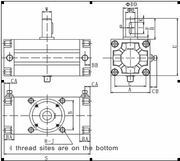
2. Pneumatic actuator
The actuator and regulatory agency of pneumatic actuator are a unified entirety. The actuator can be divided into
diaphragm type and piston type. Piston actuator has a long stroke, and applies to where great thrust exists. While
the diaphragm actuator has a short stroke, only drives the valve pole directly. The structure of pneumatic actuator
is simple, it exports great thrust, works steadily and reliably, and it's safe and explosion proof.
Dimensions
3. Hydraulic actuator
Hydraulic actuator is small, compact and has a simple structure. With stable and reliable transmission, it is buffered
preventing impact. Use different hydraulic oil depending on needs, work safely from -45℃ to 120℃, explosion proof.
Produce great output torque, applicable to all specifications of control valve. The output torque can be accurately
adjusted by constant pressure relief valve, which includes starting and stopping the adjustment of the torque. You
can even see it from the hydraulic instruments. When confronted with unexpected situation and the power is cut off,
it can still work for once or several times through accumulator, which has special significance for long pipeline’s
automatic emergency shut-off valve and inlet blow valve.
Hydraulic actuator selection table
Product Standard Table:
Particular Requirements for Product List:
|
|||||||||||||||||||||||||||||||||||||||||||||||||||||||||||||||||||||||||||||||||||||||||||||||||||||||||||||||||||||||||||||||||||||||||||||||||||||||||||||||||||||||||||||||||||||||||||||||||||||||||||||||||||||||||||||||||||||||||||||||||||||||||||||||||||||||||||||||||||||||||||||||||||||||||||||||||||||||||||||||||||||||||||||||||||||||||||||||||||||||||||||||||||||||||||||||||||||||||||||||||||||||||||||||||||||||||||||||||||||||||||||||||||||||||||||||||||||||||||||||||||||||||||||||||||||||||||||||||||||||||||||||||||||||||||||||||||||||||||||||||||||||||||||||||||||||||||||||||||||||||||||||||||||||||||||||||||||